
Create a new case
- On the relevant project folder, click the + button.
- Enter a Case name.
- Choose a Case type, either
ConstructionorO&M. - Optional: Check Copy content from other case and select the relevant case from the dropdown to copy the case data into your new case.
- Caution: Do not copy O&M case data into a Construction case or vice versa.
- Optional: Click Add another case and repeat steps 2–4 to create multiple cases at once.
- Click Add.
Manage your cases
After you’ve created a case, you can edit, copy, or delete the case.
Edit a case
- Click the three-dot overflow menu icon on the right side of the relevant case.
- Click Edit case.
- Rename the case or move it to a different project, as required.
- Click Save case.
The edit case screen also displays case Contents—a list of the bases, assets, logistics, and personnel the case contains—as well as any Comments that have been added in the Case info section of the case’s Build tab.
Copy a case
- Click the three-dot overflow menu icon on the right side of the relevant case.
- Click Create copy.
A copy of the case is added to the same project folder or group. If you want to rename the case or move it to a different folder, follow the edit a case instructions.
Delete a case
Deleting a case is permanent and irreversible. Only delete a case you are certain you won’t need again.
- Click the three-dot overflow menu icon on the right side of the relevant case.
- Click Delete case.
- Click Delete to confirm.
Add weather data
You can add weather to bases and assets. The weather data you add to your case is used together with any weather criteria you set to simulate weather downtime.
You can add ERA5 weather data to your case, which Shoreline provides by default, or you can use your own custom data. If you want to use your own data, you first need to add weather data to your input library.
- Open a simulation case.
- Click on the Build tab.
- Click on either the Assets or Bases tab.
- Click on the relevant base or asset. Note: You can only add weather data to WTG or substation assets.
- Click on the Weather tab.
- Use ERA5 data:
- Use the map to navigate to and click on a grid square. If the square is green, the weather data is already downloaded and immediately available. If the square is transparent, you will need to download the data to your case.
- Click Use ERA5 to use the data for the entire file duration or use the date-range dropdowns to define a custom range and click Download ERA5 data from....
- Use your own weather data:
- Click Select weather from Input Library or select from the map.
- Click on the relevant weather data file.
- Use ERA5 data:
- Optional: Click Apply everywhere to apply this weather file to all assets and bases currently added to the case. Any existing weather files will be replaced.
- Click Save.
Add and manage personnel
Add personnel to your case to carry out the following tasks:
- Construction: commissioning.
- O&M: scheduled and minor corrective maintenance.
Tasks that require personnel cannot be carried out without a sufficient number of personnel.
You add personnel in groups with shared settings. A group can have any number of personnel you require.
Add personnel
- Go to Build > Personnel.
- Click + Add.
- Define the personnel parameters you require.
- Click Save.
Create a campaign - O&M only
Enable a campaign using the toggle in the Campaign card and set a start and end date. These dates will be the default start date of scheduled maintenance tasks and the fixed end date for all scheduled maintenance tasks.
You can only have one campaign period with this setting enabled.
If you’re running a campaign, you will need at least 2 personnel groups, one for within the campaign period and one for corrective maintenance outside of the campaign period.
FTE pre-calculation
Use the full-time employee (FTE) pre-calculation to determine how many personnel you would need to hire to have enough people to fill up the rotations you have defined for the groups.
On the Personnel tab of your case, click on the FTE pre-calculation box.
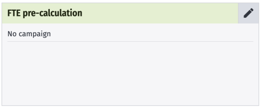
Complete the inputs and click Calculate & Save.
At the bottom of the JSON output, you will find the number of employees required as the FTEsToHire value.
When you create personnel, you will see a warning if you exceed this number.
FTE pre-calculation inputs
| Input | Description |
|---|---|
| Min. daily technicians | Number of personnel available daily. If you have enabled a campaign, you will need to enter the number of personnel available during and outside of the campaign window. |
| Campaign length | The number of days the personnel are on campaign. Automatically taken from the duration you set when creating a campaign. |
| Total hours per technician per year | The total number of hours each personnel member will work in a year. |
| Shift length for tech day (incl. breaks) | Total number of hours a personnel member will work per day, including breaks. |
| Shift length for off-days | Number of hours a personnel member is required to work per day off. |
| Days off per year | Number of days a personnel member is not available for work per year. |
| Maximum rotation cycle | Maximum rotation of days on and off work. |
Add and manage logistics
After you have added logistics to your input library you can add them to your cases, defining the number of instances you require and customizing the inputs as required.
Add a logistic
- Go to Build > Logistics.
- Click on + Add.
- Click on the relevant logistic tab.
- Click on the logistic you want to add.
- Define the logistic settings.
- Click Next.
- Complete the logistic inputs as required, these include logistic tasks and weather data. Check our logistics inputs page for a full rundown of the available inputs.
- Click Add.
Logistic settings
| Setting | Description |
|---|---|
| Name | A name for the logistic. |
| Number of units to add | How many logistic instances you want to create with the same settings. |
| Off duty location | Set where the logistic will remain when not transporting personnel. |
| Onshore heliport | Set where the helicopter takes from and returns to onshore. |
| Port | The home base of the logistic. |
| Mother vessel | The logistic to which this logistic belongs and from where it launches. |
| Logistics lead time | Time required to prepare the vessel prior to deployment. Lead time begins upon creation of work order. Any additional tasks assigned to the towing vessel during the lead time are bundled together and carried out by the logistic in a single charter period. Upon completion of the bundled tasks, the towing vessel demobilizes, the charter period ends, and a new lead time is triggered by the next task requiring a towing vessel. |
| Spot chartered | Whether the logistic has a lead time between task creation and work beginning. You can set the lead time in the logistic’s Activity durations tab. |
| Availability | The daily availability of the vessel. |
| Alter vessel settings | Whether the logistic's availability is constant or not. by date and the settings will repeat annually: The logistic is only available within the defined period. periodically and specify durations by number of days: Set the number of consecutive days on and off that occur in a rotation. |
| Wind farms | Check on which wind farms the logistic can operate. |
Other logistic options
Click on a logistic in your case at any time to access the logistic inputs and make any required modifications.
Click on the three-dot menu icon to access additional options:
- Replace
- Select a different logistic from your input library to replace the current.
- This overwrites all logistic inputs.
- Save to input library
- Make the logistic with its inputs available for use in other cases and by other team members with input library access (contact your account admin if you require this permission).
- Create duplicate on case
- Copies all logistic inputs.
- Remove from case
Configure processes
This page explains how to add and configure processes in cases, to learn about how processes work, see our Processes concept page
Configure the duration and logic of logistic installation and transit processes to accurately model installation time frames. You can set up processes on logistics at the input-library or the case level.
Processes are available on the following logistics:
- Heavy lift vessel
- Cable installation vessel
- Towing vessel
- Crane
- Anchor handling vessel
- Feeder
- Component transfer vessel
Configure a process
- Open a Shoreline Design case or go to your input library.
- If you’re in a case, click on the Build tab.
- Click on the Logistics tab.
- Click on the relevant logistic tab and card.
- Click on the Processes tab.
- Click on a process in the left-hand menu to view the stepinputs and adjust them as necessary.
- Click Add step to create additional steps.
- Use the three-dot menu icon to access additional options for each step, including choosing which weather limitations are available on the step.
- For full details on the process inputs, see our Processes concept page.
- Click Save.
Add a variation
Process variations are copies of a process which you can link to a specific asset task.
- From the Processes section of a logistic, click the + Add variation button.
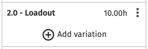
- Enter a name.
- Click Submit.
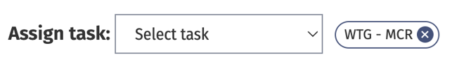
- Link the variation to a task using the Select task dropdown. If you don’t assign a task here, the variation is not used in the simulation.
- Edit the other process inputs as required and click Save.
Model floating installations with two-vessel spreads
On floating wind farm installation projects, support vessels work alongside a large installation vessel to carry out the station-keeping and hookup of a floating turbine.
In Shoreline Design, you can model this scenario using an HLV as the installation vessel and a feeder vessel as the support vessel.
You will need a case set up with a base, WTGs, a HLV, and a feeder vessel.
Configure your HLV
- Click on the Build tab.
- Click on the Logistics tab.
- Click on your heavy lift vessel.
- Click on the Processes tab.
- Click on 5.0 - Working with feeder.
- Set a Duration that meets the time required for station-keeping, i.e., anchoring and mooring, operations (~11 hours).
- Click on 6.0 - Install component.
- Set a Duration that meets the time required for hookup operations (~32 hours).
- Click Save.
Configure your feeder vessel
- Click on the Build tab.
- Click on the Logistics tab.
- Click on your feeder vessel.
- Click on the Processes tab.
- Set Duration values on 1.0 - Mobilization, 2.0 - Loadout, and 5.0 - Demobilization.
Configure asset tasks
- Click on the Build tab.
- Click on the Assets tab.
- Click on your WTG assets.
- Click on the Tasks tab.
- Click + Add task.
- Enter the following details:
- Name: Hookup operation
- Task type:
Installation – Bottom Fixed: Feeder - Logistics: Select the HLV you have configured for this purpose.
- Click + Add task.
- Enter the following details:
- Name:
Station-keeping operation - Loadout base: Select the relevant base.
- Task type:
Feeder - Dependent task:
Hookup operation - Logistics: Select the feeder vessel you configured for this operation.
- Name:
Configure helicopter daylight restrictions
By default, a helicopter can only work during daylight hours.
You can toggle the daylight restriction off in the helicopter's settings.
In order for the daylight restrictions to work properly, it is important that you set the correct time zone for your wind farm. This is done via the Build > Strategy tab.
Once you have set the time zone, the helicopter will be restricted to only fly during daylight.
When running a simulation, the Shoresim engine uses the time zone and the latitude and longitude of the helicopter's home base to calculate the sunrise and sunset times for that specific location. This allows for accurate daylight hour calculations for any location globally, even for different locations within the same time zone.
Create and apply time restrictions
Create working hours and date restrictions to define the time during which vessels cannot operate. Create time restrictions and apply the restrictions to the relevant logistics all within the Logistics tab of your cases.
Restrictions can apply for a variety of reasons, for example:
- Whale migrations
- Local laws
- Logistical or personnel limitations
You can set restrictions at any granularity:
- Hours within a day or week
- Certain days of the week
- Entire weeks or months
Applicable logistics
You can apply date and time restrictions to the following logistics:
- Design Construction:
- Component transfer vessel
- Heavy lift vessel
- Crane
- Towing vessel
- Cable installation vessel
- Anchor handling vessel
- Feeder vessel
- Design O&M:
- Crane
- Towing vessel
- Heavy lift vessel
Create a time restriction
These instructions assume you have configured a case with logistics.
- Open the relevant Shoreline Design case.
- Click on the Logistics tab.
- Click on the relevant logistic.
- Click on the Time restrictions tab.
- Click + Add restriction.
- Enter a
Restriction name. You will reference this later when you apply a restriction to a vessel. - Select a Restriction type:
- Weekly restriction: Repeats weekly and applies throughout the entire operation.
- Date range: Applies only across the specified dates.
- If you selected Weekly restriction:
- Select All day or Time ranges:
- All day: Applies through the entire 24-hour period on the selected days.
- Time ranges: Applies only across the specified time ranges. Add multiple time ranges using the + button. See How time restrictions work for more details.
- Select the Weekdays on which the restriction applies.
- Select All day or Time ranges:
- If you selected Date range:
- Select a start and end date.
- Select All day or Time ranges: All day: Applies through the entire 24-hour period on every day within your selected date range. Time ranges: Applies only across the specified time ranges. Add multiple time ranges using the + button. See How time restrictions work for more details.
- Click the green tick icon to save your restriction.
- Add further restrictions using the + Add time restriction button.
You can edit or remove a restriction using the pencil or cross icons on the right side of your table of restrictions.
Apply a time restriction
After you create a time restriction on a logistic, you can apply the restriction to the same logistic.
- Click on the Logistics tab.
- Click on the relevant logistic.
- Click on the Processes tab.
- Navigate to the relevant step in your process.
- Click the three-dot additional actions button.
- Under Time restrictions, check the relevant restrictions.
- Click Apply.
Bulk apply time restrictions
You can apply time restrictions to all steps in a process using the Bulk manage limitations feature.
- Click on the Logistics tab.
- Click on the relevant logistic.
- Click on the Processes tab.
- Next to the relevant process in the left-hand menu, click the three-dot icon.
- Click Bulk manage limitations.
- Check the relevant time restrictions.
- Click Apply.
The time restrictions are now applied to all steps within the relevant process.
After you have applied your bulk limitations, if you access the Bulk manage limitations screen again, you will see that all the limitations are unchecked. They are still applied to the steps.
Remove a time restriction
You can remove a limitation from a step by accessing the three-dot menu at the top right of the step details panel and clicking Manage limitations.
Add and manage assets
After you have added assets to your input library you can add them to your cases, defining the number of asset instances and customizing the asset inputs as required.
Add an asset
- Go to Build > Assets.
- Click on + Add.
- Enter the number of asset instances you want to add to your case. Define the asset instance locations. There are three ways to do this:
- Click Define site area.
- Click Mark corners on map.
- Click three times to mark the corners of the site area on the map.
- Click Populate site.
- Click Place individually on map.
- Click on the map to mark the location for each asset instance in turn.
- Enter the coordinates manually for each asset instance.
- Click Define site area.
- Click Next.
- Complete the asset inputs as required, these include asset tasks and weather data. Check our asset inputs page for a full rundown of the available inputs.
- Click Add.
Other asset options
Click on an asset in your case at any time to access the asset inputs and make any required modifications.
Click on the three-dot menu icon to access additional options:
- Replace
- Select a different asset from your input library to replace the current asset.
- This overwrites all asset inputs.
- Asset instance locations remain the same.
- Save to input library
- Create duplicate on case
- Copies all asset inputs, such as tasks and weather.
- Duplicate asset requires new asset instance locations.
- Remove from case
Add related instances
Save time by adding asset instances (e.g., jackets) that are linked to an existing asset (e.g., a WTG) and make sure the assets are correctly connected to use the individual dependency between tasks on those assets. Related instances automatically inherit their number and locations from the parent asset.
- Open a Shoreline Design Construction case.
- Click on the Build tab.
- Click on the Assets tab.
- On the relevant asset, click the Link (related instances) icon.
- Click on the relevant related instance.
- Click on the asset type you want.
The related instances appear in the Assets tab next to the parent asset. Click on the asset to define tasks or update other asset inputs.
Configure tasks
The Tasks tab of your assets provides centralized management of the entire asset workflow, from transport and assembly, through installation, to commissioning and testing. Assign and organize asset tasks, including dependencies, to model any real-world construction scenario. These instructions require a Shoreline Design Construction case with an asset added.
Add logistics to your case before configuring asset tasks. You will need to select the logistic as part of the task configuration.
- Open your Shoreline Design Construction case.
- Click on the Build tab.
- Click on the Assets tab.
- Click on the relevant asset.
- Click on the Tasks tab.
- Click + Add task.
- Complete the task inputs.
- Learn more about the inputs on the Tasks concept page.
- Continue adding tasks as required.
- Click Save.
Add grouting
There are two ways to add grouting to your case:
- Use a single HLV and add grouting as part of the WTG installation process:
- Model the time required for grouting without any other additions to your case.
- Create a dedicated grouting HLV:
- Model grouting tasks that appear in your case outputs.
- Requires the following additions:
- Create and configure a dedicated HLV for grouting.
- Add a jacket, pile, monopile, or foundation asset.
- Create an asset grouting task and link it to the asset installation task.
Add grouting as part of the WTG installation process
Grouting will not appear in your outputs, but the process will occur and contribute to your project duration.
These steps require a case configured with an HLV.
- Open a Design Construction case
- Click on the Build tab.
- Click on the Logistics tab.
- Click on the HLV.
- Click on the Processes tab.
- Click on 6.0 - Install Component.
- Click + Add step.
- Name the step, e.g.,
Grouting. - Enter a Duration value and any Required weather window and Weather criteria.
- Click Save.
Create a dedicated grouting HLV
Once you’ve added either a jacket, monopile, pile, or foundation asset to your case, as well as a dedicated grouting HLV, you can add an HLV grouting process and an asset grouting task to model grouting.
These grouting tasks will appear in your case outputs after you run a simulation.
- Open a Design Construction case.
- Click on the Build tab.
- Click on the Logistics tab.
- Click on the grouting HLV.
- Click on the Processes tab.
- Under 7.0 - Grouting component, enter a Duration value and any Required weather window and Weather criteria.
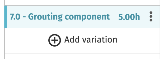
- Click Save.
- Click on the Assets tab.
- Click on either the jacket, monopile, pile, or foundation asset.
- Click on the Tasks tab.
- Click + Add task.
- Complete the task inputs:
- From the Task type dropdown, select Grouting: Shuttle.
- Select a Loadout base.
- Set the Dependent task as the installation task.
- Enter a Maximum delay.
- Note: Enter a value that is higher than the grouting component duration set on the HLV process in step 6.
- Select the dedicated grouting HLV as the Logistics for the task.
- Click Save.
Add cables
There are two types of cables you can add to your cases:
- Inter-array cables
- Export cables
Power from turbines is transported by inter-array cables to the substation. From the substation, export cables carry the power to shore.
After you have added cables to your case, you can further model cable laying and burial.
- Open a Shoreline Design case.
- Click on the Build tab.
- Click on the Assets tab.
- Click + Add.
- Click on either Inter array cable or Export cable.
- Enter the number of cables you want to add.
- Enter the cable-specific inputs:
- For inter-array cables:
- Set which WTGs the cables connect using the dropdowns.
- Optional: enter a
Length (m)(default is the distance between the WTGs) and aPower capacity (MW).- See our Model system-level reliability page for how you can use the Power capacity input.
- For export cables:
- Select the asset from which the cable exports power.
- Enter the
LongitudeandLatitudeof the cable endpoint. - Optional: enter a
Length (m)(default is the distance between the asset and aPower capacity (MW).- See our Model system-level reliability page for how you can use the Power capacity input.
- For inter-array cables:
- Click Next.
- Enter any asset inputs you require.
- Click Save.
Model cable laying and burial
After you have added cables to your case, you can create tasks to model cable laying and burial.
These instructions require a case with WTGs, cables, a cable-installation vessel, and an anchor-handling vessel.
- Open a Shoreline Design case with cables.
- Click on the Build tab.
- Click on the Assets tab.
- Click on the relevant cable asset.
- Click on the Tasks tab.
- Click + Add task.
- From the Task type dropdown, select either Cable laying or Cable burial.
- Select a Loadout base.
- Add task dependencies so that, e.g., the cable laying can’t take place until all your WTGs are installed and the cable burial must wait until the cable laying is complete.
- Select an Anchor handling towing vessel and a Cable installation vessel.
- Click Save.
Model a major component replacement
Major component replacements (MCRs) are configured in Shoreline O&M simulations as corrective maintenance tasks using either an HLV or a towing vessel.
MCRs are modelled as follows:
- Add a corrective maintenance task on an asset.
- Set the task to use an HLV or a towing vessel, depending on whether the maintenance work occurs on site or back at port.
- If you’re using a CTV, check the Dedicated tasks option on the logistic.
- If you're using a towing vessel, add an onshore crane to your case to conduct the maintenance work.
- Add any lead times you require.
- Optionally, enable continuous disconnection on your towing vessel.
To follow these instructions, you will need a case configured with the following:
- A base
- A WTG asset
- For a fixed-bottom MCR:
- An HLV
- A dedicated CTV
- For a floating MCR:
- A towing vessel
- An onshore crane
Create an MCR task
You first need to create the MCR task on the asset as a corrective maintenance task.
- Click on the Build tab.
- Click on the Assets tab.
- Click on your WTG asset.
- Click on the Corrective Maintenance tab.
- Click + Add corrective maintenance.
- Complete the inputs for the MCR.
- Severity should always be set to
Criticalfor an MCR. - For Logistics, check either Heavy Lift Vessel or Towing vessel.
- Complete the HLV- or towing-vessel specific inputs.
- Severity should always be set to
- Click Save.
Add lead times
Lead times determine the length of preparation time required before work on the MCR task can begin or before a logistic can leave base to begin work after receiving a work order.
Lead time are considered separately and occur consecutively.
There are 3 lead times:
- CTV lead time
- Model spot-chartered vessels that require preparation time.
- Available on CTVs, SOVs, helicopters, and daughter craft.
- Set in the logistic’s Activity durations tab.
- Only takes effect when the Spot chartered option is checked on the logistic.
- Logistic lead time (HLV and towing vessel)
- Set at the logistic member level or when first adding the logistic to your case.
- Applies to the logistic when conducting an MCR.
- Occurs once per charter period.
- The process for an MCR:
- Lead time triggered upon task creation.
- Any additional tasks assigned to the logistic during the lead time are bundled together and carried out by the logistic in a single charter period.
- Upon completion of the bundled maintenance tasks, the logistic demobilizes and the charter period ends.
- A new lead time is triggered by the next maintenance task that requires the logistic.
- Task lead time
- Applies at the task level, i.e., regardless of the logistic used.
- Applies to every task.
Add CTV lead time
- Open a Shoreline Design O&M case.
- Click on the Build tab.
- Click on the Logistics tab.
- Add a new, or click on an existing, CTV.
- If adding a new logistic:
- Check the Spot chartered option.
- Click Save.
- If editing an existing logistic:
- Click on the logistic in the Members tab.
- Check Spot chartered.
- Click Save.
- If adding a new logistic:
- Click on the Activity Durations tab.
- Enter a value for the Lead time.
- Click Add (if creating a new logistic) or Save (if editing an existing logistic).
Add logistics lead time (HLV and towing vessel)
- Open a Shoreline Design O&M case.
- Click on the Build tab.
- Click on the Logistics tab.
- Add a new, or click on an existing, HLV or towing vessel.
- If adding a new HLV or towing vessel:
- Enter a value for the Logistics lead time.
- Click Next.
- Make any required changes to the other settings.
- Click Add.
- If editing an existing HLV or towing vessel:
- Click on the logistic in the Members tab.
- Enter a value for the Logistics lead time.
- Click Save.
- Click Save again.
- If adding a new HLV or towing vessel:
Add task lead time
- Open a Shoreline Design O&M case.
- Click on the Build tab.
- Click on the Assets tab.
- Click on the relevant WTG asset or add a new one.
- Click on the Corrective Maintenance tab.
- Create or click on a maintenance task.
- Enter a value for the Task lead time.
- Click Save.
Optional: Allow continuous disconnection on the towing vessel
By default, the towing vessel will tow an asset instance out, hook it up, return to port, then travel to the site again to unhook and tow back the next asset instance. If you enable continuous disconnection, the towing vessel will hook up the first asset instance, then travel directly to the second asset instance and tow it back to port.
- Open a Shoreline Design O&M case.
- Click on the Build tab.
- Click on the Logistics tab.
- Add a new, or click on an existing, towing vessel.
- If adding a new towing vessel:
- Check Allow continuous disconnection.
- Click Next.
- Make changes to the inputs you require.
- Click Add.
- If editing an existing towing vessel:
- Click on the logistic in the Members tab.
- Check Allow continuous disconnection.
- Click Save.
- Click Save again.
- If adding a new towing vessel:
Model system-level reliability
Set the power capacity on cables and substations to model power loss through those assets. By adding a power limit to these assets, you can do the following:
- Simulate the prevention of system overload through reductions in power production.
- Analyze the impact of all BoP components on production-based availability.
- Understand how each component's performance, failures, and maintenance schedules affect the overall availability and efficiency of your wind farm.
You can also add foundations to your case that impact power production by adding them as related instances to the relevant asset.
If you don’t add cables to your case with power capacity inputs, the wind turbines in your case will generate power according to the windspeed and WTG power curve.
If you only have an OSS and no cables, the OSS will reduce energy production on every WTG in the wind farm to which it is connected according to the percentage you set on the maintenance activity.
Finally, if you want cables in your case without them influencing site-wide power production, you can add the cables to your case without linking them to an asset.
Configure your case for power relations
When you add any inter-array cables, export cables, or substations to your case, you can add a power capacity value at the asset instance level.
These are the requirements for the solution to work:
- Create a grid layout that connects all WTGs to an export cable or substation.
- Link each inter-array cable to a WTG instance.
- If you’re using foundation, add them as related instances.
When these criteria are met, the case will model the reliability of the configured asset instance by default when you simulate the case.
Add cables
- Open a Shoreline Design O&M case.
- Click on the Build tab.
- Click on Assets.
- Click + Add.
- Choose either an Inter array cable or Export cable asset.
- Enter the number of cables you want to add.
- In the table of asset instances, create your grid pattern by linking each cable to the relevant WTG using the dropdowns.
- Enter a value for
Power capacity (MW)on the relevant asset instances. - Click Next.
- Configure the asset as required.
- Click Save.
Add foundations
- Open a Shoreline Design O&M case.
- Click on the Build tab.
- Click on Assets.
- On the WTG asset card, click the Add related instances button.
- Choose the type of foundation you want to add.
- Choose the relevant foundation template from your input library.
Your case now has foundations added that are linked to the asset instances. When maintenance work is carried out on these foundation asset instances, it will affect the wind farm’s power production.
Analyze the system-level impact
On the Output tab of your case, under Average PBA loss per root cause, two outputs provide insight into how much downtime is caused by power throttling, whether from the wind farm exceeding the maximum power capacity or from a failure on a cable or OSS reducing a WTG’s output:
OSS at max capacityCable at max capacity
If you have added foundations, any power loss incurred through maintenance on those assets is registered under Average PBA loss per root cause by any output with External at the start, e.g., External scheduled service work.
Strategy
The Strategy tab of your Design cases provides some mandatory and some optional, more advanced features. The impact these settings have on your simulation outputs are case dependant and are best experimented with to compare results. This page provides a rundown of the available settings and suggestions on how to use them.
All of these parameters are optional and considered advanced, except for those in the general settings, which are required to run a simulation.
Case time zone
Select a time zone based on your case’s location. If you have bases or assets spanning multiple time zones, you will need to choose just one time zone.
The time zone is only used for daylight restrictions and helicopters. If your case does not feature either of these, this setting has no effect on your outputs.
Helicopters and time zones
The Shoresim engine limits helicopters to daylight flying hours, using the time zone and the latitude and longitude of the helicopter's home base to calculate the sunrise and sunset times for that specific location. This allows for accurate daylight hour calculations for any location globally, even for different locations within the same time zone.
General
These two settings are the only required strategy settings.
Emergency response limit
Set how far a transport logistic can travel from an asset while work is being conducted. It is defined in minutes: set the maximum amount of time a vessel requires to get back to a technician team in an emergency.
For example, if the emergency response time limit is 30 minutes and a technician team is dropped off at asset A, the logistic that dropped off the technician team can only access assets within a 30-minute radius of asset A.
We recommended that you set something realistic (30–60 minutes) even if your site does not legally require an emergency response limit, as it can affect your simulation results.
The effect of the emergency response limit
The effect of different values for the emergency response limit is impossible to predict. Generally, the lower the limit, the fewer tasks can be carried out simultaneously, reducing up time. Inversely—and still generally—the higher the limit, the more tasks can be carried out simultaneously, increasing up time. However, as this is a general rule, there are scenarios where a lower limit can reduce the travel time of the logistic, allowing more maintenance to be conducted in a smaller area, resulting in increased up time.
We advise you to run comparisons with slightly different values for the emergency response limit if you are interested in seeing the effect it has on your case. If the effect is minor or not noticeable, you can leave the HSE in the 30–60-minute recommended range.
Minimum working length
Set the minimum amount of work time required on an asset to dispatch a work order. This setting ensures that personnel are not transported to an asset for small time periods of work.
Technician breaks and shift lengths
Complete both fields for these settings to take effect. Define a shift length and the break time per shift. For example:
- Break time in total per work shift: 1 hour
- Work shift length: 12 hours
- Result: 11 hours of work is completed per 12-hour shift.
Technical maintenance parameters
Design Construction only.
These two settings provide a way to accommodate for technical (i.e., non-weather-related) vessel downtime. These settings will affect all major vessels (i.e., vessels that feature processes).
Loadout and installation tasks affects loadout and installation task durations and cable-laying and -burial times.
Technical maintenance parameters marine operation tasks affects all non-loadout and -installation tasks as well as transit and positioning speeds.
If you estimate, e.g., your cable installation vessel suffers 10-percent technical downtime, you can enter 10 percent in the Loadout and installation tasks setting. All loadout and installation tasks carried out by installation vessels will take 10 percent longer, simulating a 10-percent technical downtime.
Crew change strategy
Choose how crew changes occur.
If you select None, the crew is always available.
If you select At port or At SOV, there are additional parameters:
- SOV travels to port for restock/bunkering
- When checked, the
Time between going to portvalue in the SOV’s Activity durations tab is used. - If unchecked, the
Time between going to portparameter is ignored.
- When checked, the
- Crew period
- How long the crew remain on site.
- Duration of switch
- How long a crew-change operation takes to complete.
- Transport involved
- Select the logistics that carry out the crew-change operation.
Scheduling strategy
Manually configure the times when scheduling takes place. Scheduling occurs automatically by default, with a single scheduling session per day taking place at a time calculated by how long it takes an SOV to travel to the farthest WTG from its off-duty location, this generally means 1–2 hours before work begins.
The first time you set is when the scheduling for the day should happen. We recommend you set the time an hour before the first shift starts.
All subsequent scheduling times are when you'd like the simulation to reschedule any tasks that remain for the day. Rescheduling only occurs when a critical corrective maintenance task happens that day. If no critical corrective maintenance task occurs that day, the simulation continues based off the first schedule.
Notes:
- The simulation engine only schedules on the hour.
- The time format changes depending on your local computer settings, but when a simulation is run, it reads the time in 24-hour format.
Work order priority
Set the priority of different work order types.
While these settings are mostly applicable to Design O&M, you can set the priority on installation and commissioning tasks in Design Construction, as well.
Expand a dropdown for one of the task types and you will see the available priorities. Click and drag on the six-dot icon to reorder the priorities. Click Add/Remove priority to see any available, unused priorities and use the + and – icons next to a priority to add or remove it from the list.
There are two additional checkboxes:
- Bundle work orders on assets
- If an asset has just had a work order scheduled on it, any further work orders assigned to that asset will be prioritized so the work orders can be dispatched together.
- Redeploy personnel
- Personnel on site can move to another work order on site without having to return to base.
- We recommend also checking Bundle work orders on assets if you check this setting.
Task and work order types
There are different task types between Design Construction and Design O&M. Task types are prioritized in the order listed (e.g., installation tasks take priority over commissioning tasks). You can set the priority of tasks within each task type.
- Design Construction:
- Installation
- Commissioning
- Design O&M:
- Major corrective
- Minor corrective
- Started scheduled tasks
- Non-started scheduled tasks
The prioritization options are listed in the table below.
| Task priority | Description |
|---|---|
| Task step priority | Tasks with the lowest task step number are prioritized. |
| Shortest remaining repair time | Time remaining to complete the task. |
| Longest remaining repair time | Time remaining to complete the task. |
| Started and unfinished work orders | Work orders that have been started but not yet completed are prioritized. |
| Highest asset priority | Assets with the highest priority are prioritized. Asset priorities are set in the Members tab of the asset. See the WTG input data page for more details. |
| Earliest created | The first task to have been created is prioritized. |
| Severity priority | Tasks with critical severity are prioritized. |
| Distance to other critical tasks | Task with the shortest overall (summed) distance to all other critical tasks is prioritized. |
| Largest repair team size | Sum of the roles and skills required to complete the task. |
Learning curve
For any loadout and installation tasks with durations set in a logistic’s Processes tab and the learning curve enabled, the learning curve counts the number of times the task is carried out and multiplies the input duration of the task by the activity time percentage for each cycle.
In the example screenshot below, the first time the task (e.g. WTG installation) is carried out, it will take 50 percent longer than the task duration set. The second time the task is carried out, it will take 25 percent longer. The third time this task is performed, it will take the time set as the task duration.
The last value that you enter, 100 in the example above, is used for all subsequent tasks, so in this example any tasks after cycle 3 will continue to take the time set as the task duration.
If you leave gaps between cycle numbers then the values for intermediary cycles are interpolated, e.g., if only enter values for cycles 1 and 5, then the time percentages for cycles 2, 3, and 4 are interpolated from the values you enter for 1 and 5.